Matthew's Amplifier Project
From the archives...circa late 1999...
I have upgraded the html and page style, but it's still an older style page.
The sound clips at the bottom are pretty cool, though.
Here you will read the story and (most importantly) see the pictures of Matt building his dream guitar amplifier. It all started with a visit to the Allen Amps web page. Then Matt bought a kit from David Allen (with a couple of upgrades/modifications) and the whole thing got going. From personal experience, David Allen is a nice guy, very helpful, and sells good stuff. Here we go...
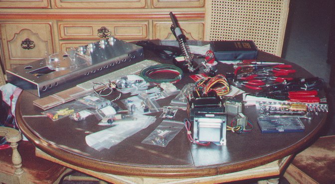
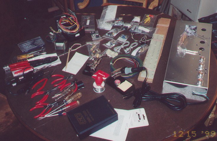
The first two pictures show the parts set up on the Dining Room Table. That's a lot of stuff, and felt kind of intimidating.
Once we figured out that everything was there, Matt got to work. Quick story: a few parts were missing, Matt gave David a quick call, and the parts came in the mail quickly. The first thing to do was assemble the chassis by installing the tube sockets, potentiometers, jacks, switches, pilot light, transformers, and so on.
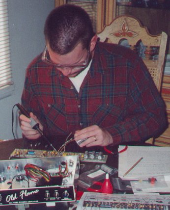
Once the knobs were put on, it was time to run the ground wires under the circuit board and get ready to solder the board together. Notice that I labeled all of the resistors by sticking one of the wire ends into a piece of paper after reading the color code and rechecking the values with a meter.
It gets a lot easier after the first few hours... Once you learn how to desolder a bad connection and re-solder it correctly, it's easy. Thankfully, it didn't take too long and I learned how to do it right the first time. then it went much faster.
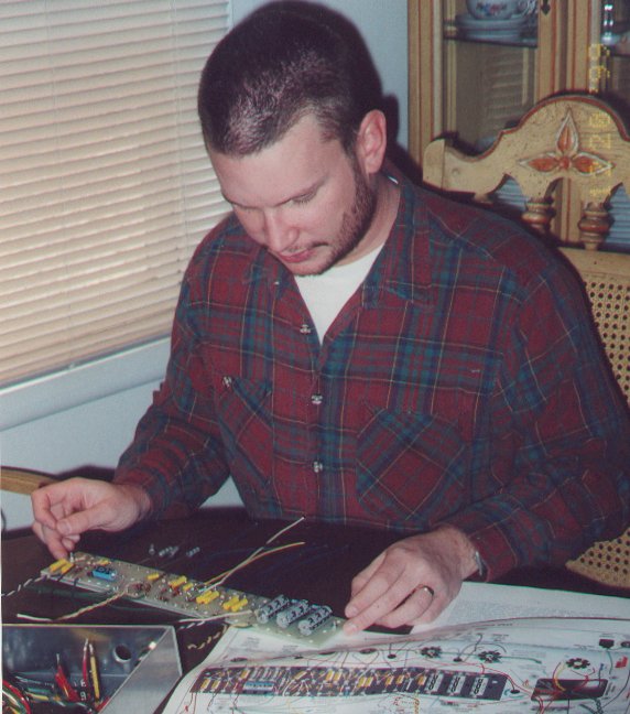
After several days of soldering and hand-wiring a point-to-point circuit board, I carefully checked, double checked, and triple checked every connection with the handy full-color layout diagram and the schematic to ensure the correct components were in the right places. I had to desolder 2 capacitors and switch them--oops! Glad I caught it at this stage.
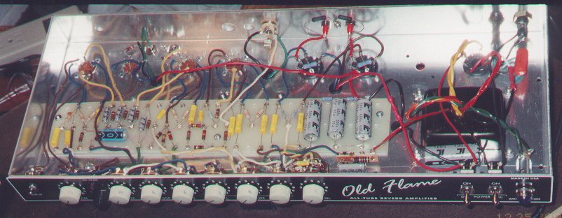
Here's the circuit board installed in the chassis with all of the leads dressed and attached. The only thing missing at this moment are the heater wires for the tubes. Notice I carefully installed all of the components with the values facing up for easy troubleshooting if needed in the future--I intentionally took the picture so you can't read them all here--buy a kit from David if you want to use the circuit. I did have to crimp a little extra wire on to the red lead from the output transformer as the lead was too short to reach the DC power switch. Also, notice the cloth-covered wire--I had never worked with this stuff before, and I love it! It is much easier then the current standard stuff--just cut to length and push the cloth back--easy and quick.
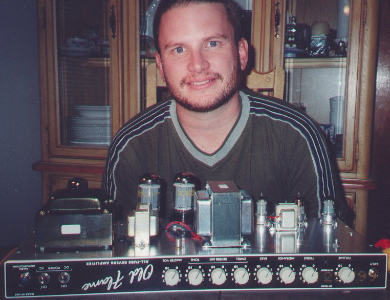
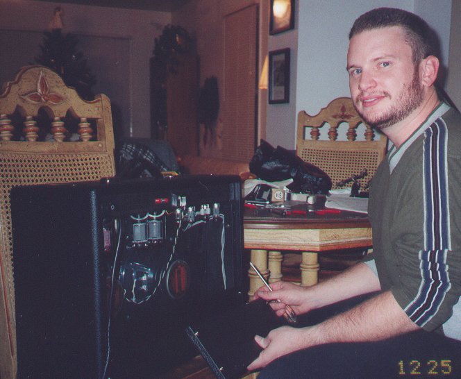
Once I was done with all of the connections, and checked them 3 times again, it was time to install some tubes and turn it on for the first time. Talk about nervous--the picture was taken after it worked right the first time and I biased the power tubes. Here's what it has in it: (left to right in photo) 5AR4 rectifier (Chinese) (Note: a solid state rectifier is included with the kit for those that prefer them), 2 Westinghouse labeled US made 6L6GC's, 2 Sylvania US made JAN 12AX7WA'a, and 2 Raytheon labeled US made 12AT7's. Total output with the tube rectifier is about 40 watts. Also, I ordered the upgraded output transformer for better bass at full volume--no mushy or muddy sounds here! Note the handy bias control knob near the front of the chassis just above (or is that below) the Master Volume. The kit includes bias probe jacks for the rear of the chassis so that removing the chassis is not necessary for bias adjustments.
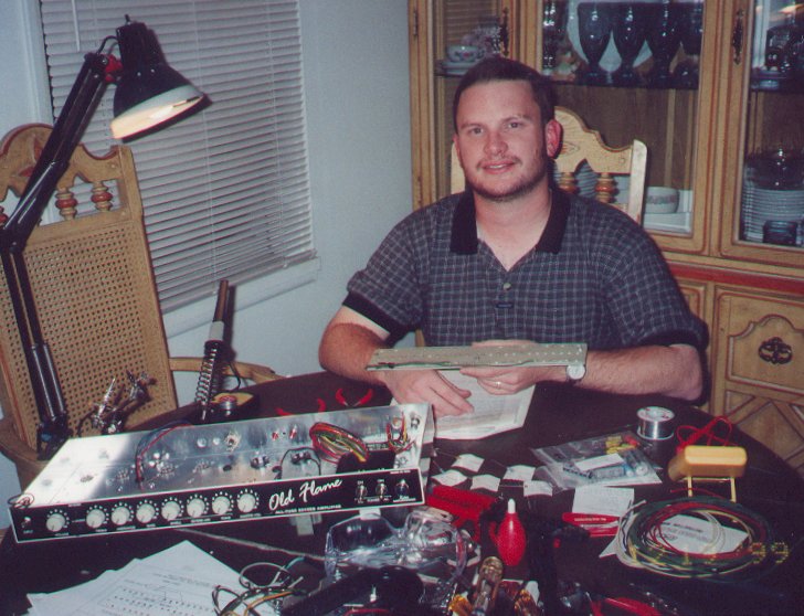
After confirming the chassis was built correctly, it was time to install it into the cabinet with the speakers. I ordered the cabinet with 2 10" Jensen reissue C-10Q's. Once the chassis was installed, I hooked up the speakers and the reverb tank and we were in business. Here I am installing the last of the back panels.
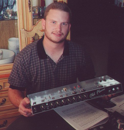
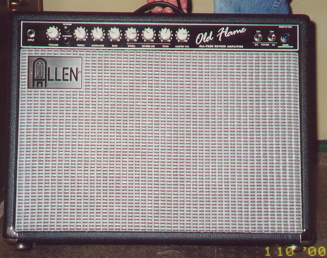
Here's the last photo: The finished product from the front. My favorite parts: the amplifier combines the clean sound of a blackface Fender with the 3 knob reverb of the Fender stand-alone reverb and a couple of fun additions: switches in the front for easy accessibility, a bright switch, a master volume for "crunchy" rhythm sounds, and a "raw" switch that bypasses the tone circuitry and sends the whole signal to the preamp circuit producing a serious gain boost.
Finally, a little personal touch, a blue pilot light jewel.
- It is now April 2000 and I am still in love with this amp! In fact, I like it better today than I did when I first
built it. The Jensen Reissue C10Q's were a little bright when I first built the amp and made the gain sounds a
little too trebley for my taste. Now, however, the speakers have broken in nicely and are warm and smooth--exactly
what I always wanted! I use the bright switch from time to time when playing clean for a little extra "cutting
through the mix" ability, but whether the bright switch is on or off the amp sounds great clean, and as an incredible bonus, now that the speakers have broken in, the higher gain sounds are wonderfully warm and rich and fabulous. This is a purchase that I don't believe I will ever regret. Again, please feel free to email me with any questions or comments. Also, I bought some Fender tilt back legs (14 inch) and got out the power drill--yep, I drilled into my solid, finger-jointed pine cabinet and put the legs on. Sorry I don't have a photo, but it looks like any similar-sized Fender amp when tilted back. I don't use the tilt back legs when playing out, but it is a nice feature in my living room.
- May 2000. I replaced the raw switch with a mini-pot (supplied by David Allen) and I love the versatility--I can dial in varying degrees of "rawness." Also, I made changes to my circuit (that are now standard in the newest update
to the amp that is being sold today) for slightly more headroom. Still in love with this amp! This is why I wanted a point-to-point in the first place--ease of experimentation and modification, etc.
- August 2000. I replaced the Chinese 5AR4/GZ34 rectifier tube with the solid state rectifier that David Allen supplied. I didn't like it as well. I then put in a Russian 5U4G rectifier and liked it even more than the 5AR4. I have always preferred the "sag" of an old Fender Super Reverb over a Vibrolux Reverb, and the rectifier change provided it.
Still love this amp!
- February 2001. I have had several people ask me for sound clips of the Old Flame. Below are some MP3's, each with details on the amp's settings. Some notes: First, all the clips were recorded with my 1995 Fender Tele Special--look at my guitar page for details about it--and no effects of any kind were used. I just plugged straight into the amp and twisted the knobs. Then I put a Shure SM-57 in front of the amp and recorded the samples on my Tascam 424mkII four track. I only used one track--it's just me and the guitar and amp, no overdubs, etc. Each clip is about 25 to 35 seconds long.
- You will notice that for many of the samples I only made small changes in the settings. I've found some settings I really like, so, for example, I don't move the reverb or tone knobs too often--really, I just didn't think about it. Also, I'm not the world's greatest guitarest (*unless you ask my wife), so if you find a mistake in my playing, just chuckle with me and let it go--no need to point it out and make me self-conscious. Also, I tried to play simple things, some recognizable, some extemporaneous creations while the tape was rolling. My goal was not to impress with guitar playing prowess, but to let you hear the amp itself. Bear in mind, this is what my amp sounded like on this day with the specific tubes I had in it and with me playing. Your mileage may vary (and may improve, depending on who's driving).
- Finally, on a couple of the cleaner examples you will hear some distortion--that's because I mixed down to my computer's sound card line in, and I have a cheap sound card that started to overdrive. I tried to
get around that on My Typical Setting 2 by lowering the input volume, but all it did was make it sound a little bit muted. Oh, well--an MP3 will only get you so far anyway...and they're good enough for you to get the idea. Let me know what you think and thanks for stopping by. Oh, yeah, all the knobs are numbered 1 to 10, except the raw knob--it has no numbers, but it has 11 detent positions that I will call 1-11. Yeah, yeah, that knob goes to 11.
- NOTE: Now it is 2005...the sound clips aren't here anymore...sorry. Maybe I'll get them back up someday if I find the mp3's.
- Back again, now in 2007. Woo hoo! I found the clips. I also found a few more sound files I recorded while testing some microphones and stuff. They are also recorded with the Allen, but I don't have a list of the settings or anything. I also did a major cleanup of the 8 year old html and style of the page. I think I'll leave the content as-is for the moment, though.
My Typical Setting 1, bridge single coil
Old Flame settings: (
volume: 2,
raw: 1,
bright: off,
treble: 2,
mid: 4,
bass: 3,
dwell: 6,
mix: 3,
tone: 4,
master volume: 4)
My Typical Setting 2, neck humbucker
Old Flame settings: (
volume: 2,
raw: 1,
bright: off,
treble: 2,
mid: 4,
bass: 3,
dwell: 6,
mix: 3,
tone: 4,
master volume: 4)
I Wish I Could Play Jazz, neck humbucker
Old Flame settings: (
volume: 2,
raw: 1,
bright: off,
treble: 2,
mid: 4,
bass: 3,
dwell: 6,
mix: 3,
tone: 4,
master volume: 5)
Blue Thang, bridge single coil
Old Flame settings: (
volume: 4.5,
raw: 1,
bright: off,
treble: 2,
mid: 4,
bass: 3,
dwell: 6,
mix: 3,
tone: 4,
master volume: 4)
Amazing Grace, bridge single coil
Old Flame settings: (
volume: 3,
raw: 3,
bright: off,
treble: 2,
mid: 4,
bass: 3,
dwell: 6,
mix: 3,
tone: 4,
master volume: 4)
Satisfaction Plus, This one was just me goofing around a little.
The End of the Tape, The tape was pretty nearly out, so I played around for a minute or two. I think this is the best off the batch of samples...it has two tracks.

